


Plate load test (PLT)
1. Purpose
Plate load test was performed to directly estimate the settlement potential of footing.
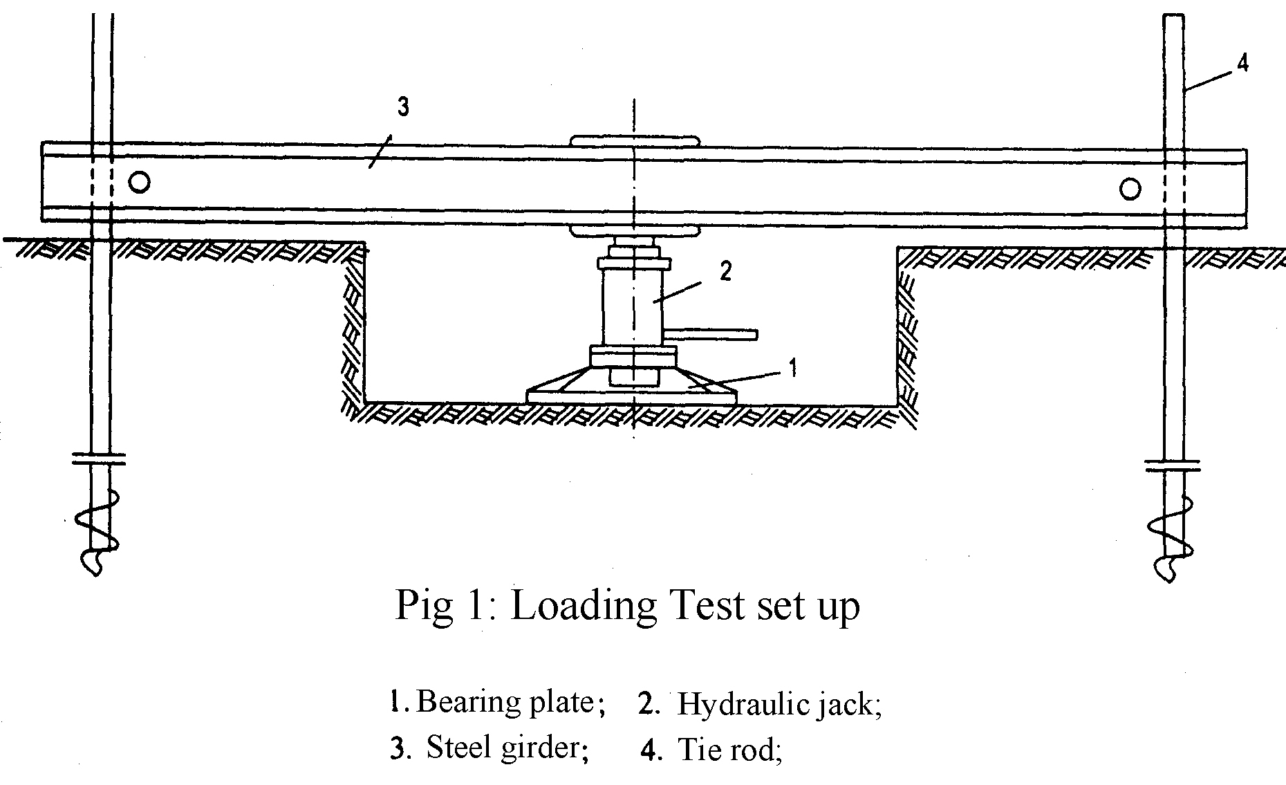
2. Testing method
Round steel plate: diameter B = 56.4 cm, area S = 2500 cm2.
Jack: max vertical pressure P = 25 tons with pressure gauge.
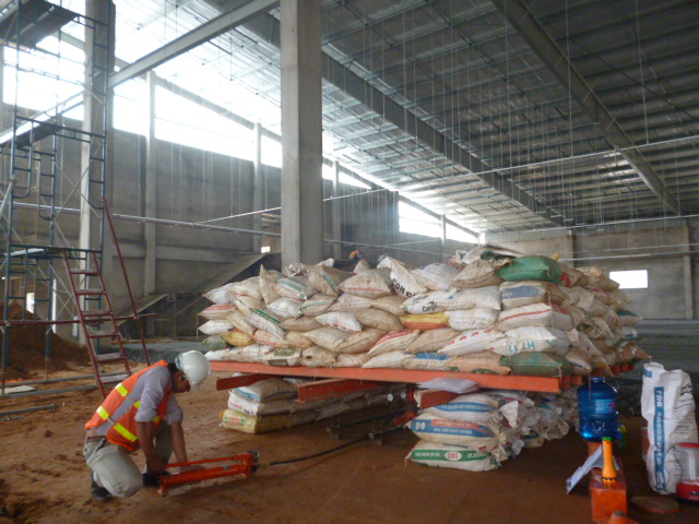
Counter balance: creating by sand bags is arranged on steel board. The board is made by steel beams I 100 and steel pipes D=130mm, dimension 2.4mx4.0m. Total of load are 10 tons.
Dial gauge: using 03 gauges made in Japan with 0.01mm accurately.
3. Testing standard
According to standard ASTM D1194 - 94.
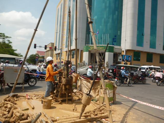
4. Procedure
The testing was carried out on a level surface excavated in a test pit. A round steel plate was pushed into the soil. The plate was placed at the center of the hole. Load to the plate was applied in steps by means of a jack for good soil (0.0 – 0.5 – 1.0 – 1.5 – 2.0 – 2.5 – 3.0 – 3.5 – 4.0 ...kg/cm2).
For soft soil (clay soft, clay very soft) (0.0 – 0.25 – 0.5 – 0.75 – 1.0 – 1.25 ...kg/cm2).
During each step load application, the settlement of the plate was observed using dial gauges. Time interval of loading was from 01 hour to 03 hours and distributed to read as follows: 10 minutes - 10 minutes - 10 minutes - 15 minutes - 15 minutes - 30 minutes - 30 minutes - 30 minutes - 30 minutes.
Experiment stopped when steady strain with the last load of at the request or the total strain at 0.15d where d is the diameter of compression plate.
After failure, unload to the plate was also applied in steps by means of a jack for good soil (…– 3.5 – 3.0 – 2.5 – 2.0 – 1.5 – 1.0 – 0.5 – 0.0kg/cm2), for soft soil (…– 1.0 – 0.75 – 0.5 – 0.25 – 0.0kg/cm2).
Unload time of each step was applied was 30 minutes and distributed to read as follows: 10 minutes - 10 minutes - 10 minutes.
The stress versus depth of penetration data is then used to calculate the subgraded modulus E. The procedure is to plot the stress on the plate versus the penetration of the plate. Using this plot, the yield point at which the penetration rapidly increases is estimated. Then the stress (q) and depth of penetration of the plate (s) corresponding to the yield point are determined from the plot.
5. Calculation
The subgraded modulus E is calculated according to formula as follows:
![]()
Where:
E: Subgraded modulus (kG/cm2)
q: Stress (in the yield point) (kG/cm2)
B: Diameter of plate = 56.4 cm
v: Poisson’s ratio = 0.35
s: Depth of penetration of the plate (in the yield point) (cm)
The ultimate load-bearing capacity of foundation can be effectively determined from the field plate load test.
For tests in cohesive soil:
Qu (F) = Qu (P)
Where:
Qu (F) = ultimate bearing capacity of the proposed foundation
Qu (P) = ultimate bearing capacity of the test plate (in the yield point)
The allowable load-bearing capacity of foundation:
Qa (F) = Qu (F) x FS with FS = 0.75
Categorys
Faacebook
Facebook H.A.I