


Physico-mechanical test
PHYSICO-MECHANICAL TEST
1. WATER CONTENT DETERMINATION
Purpose: This test is performed to determine the water (moisture) content of soils. The water content is the ratio, expressed as a percentage, of the mass of “pore” or “free” water in a given mass of soil to the mass of the dry soil solids.
Standard Reference: ASTM D 2216 - Standard Test Method for Laboratory Determination of Water (Moisture) Content of Soil, Rock, and Soil-Aggregate Mixtures
Significance: For many soils, the water content may be an extremely important index used for establishing the relationship between the way a soil behaves and its properties. The consistency of a fine-grained soil largely depends on its water content. The water content is also used in expressing the phase relationships of air, water, and solids in a given volume of soil.
Equipment: Drying oven, Balance, Moisture can, Gloves, Spatula. 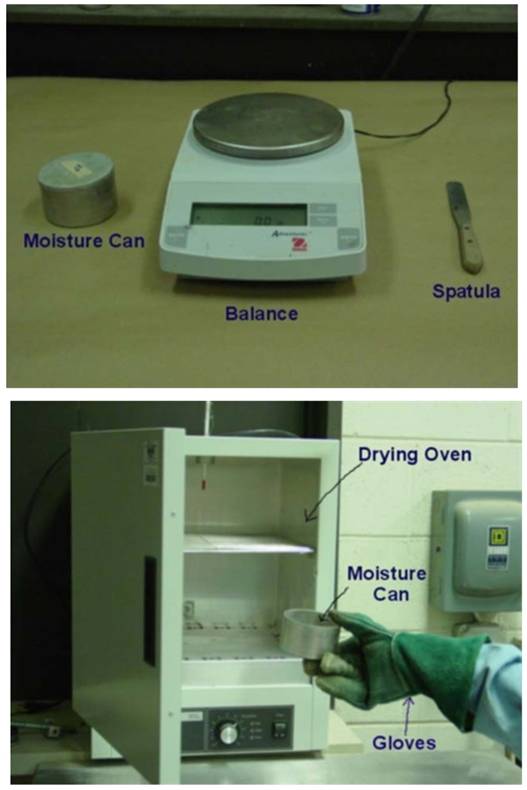
Test Procedure:
(1) Record the moisture can and lid number. Determine and record the mass of an empty, clean, and dry moisture can with its lid (MC)
(2) Place the moist soil in the moisture can and secure the lid. Determine and record the mass of the moisture can (now containing the moist soil) with the lid (MCMS).
(3) Remove the lid and place the moisture can (containing the moist soil) in the drying oven that is set at 105 °C. Leave it in the oven overnight.
(4) Remove the moisture can. Carefully but securely, replace the lid on the moisture can using gloves, and allow it to cool to room temperature. Determine and record the mass of the moisture can and lid (containing the dry soil) (MCDS).
(5) Empty the moisture can and clean the can and lid.
Data Analysis:
(1) Determine the mass of soil solids.
MS = MCDS − MSC
(2)Determine the mass of pore water.
MW = MCMS− MCDS
(3) Determine the water content.
w = (MW /MS) x 100
2. DENSITY (UNIT WEIGHT) DETERMINATIOM
Purpose: This lab is performed to determine the in-place density of undisturbed soil obtained by pushing or drilling a thin-walled cylinder. The bulk density is the ratio of mass of moist soil to the volume of the soil sample, and the dry density is the ratio of the mass of the dry soil to the volume the soil sample.
Standard Reference: ASTM D 2937-00 - Standard Test for Density of Soil in Place by the DriveCylinder Method
Significance: This test is used to determine the in-place density of soils. This test can also be used to determine density of compacted soils used in the construction of structural fills, highway embankments, or earth dams. This method is not recommended for organic or friable soils.
Equipment: Straightedge, Balance, Moisture can, Drying oven, Vernier caliper 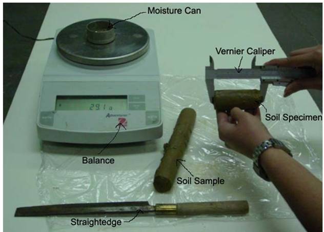
Test Procedure:
(1) Extrude the soil sample from the cylinder using the extruder.
(2) Cut a representative soil specimen from the extruded sample.
(3) Determine and record the length (L), diameter (D) and mass (Mt) of the soil specimen.
(4) Determine and record the moisture content of the soil (w). (See Experiment 1)
Data Analysis:
(1) Determine the moisture content as in Experiment 1
(2) Determine the volume of the soil sample
V=(πD²L)/4 (cm³)
(3) Calculate bulk density (ρt) of soil
ρt = Mt/V (g/cm³)
or unit weight γt = ρtg
(4) Calculate dry density (ρd) of soil
ρd = ρt /(1 + w) (g/cm³)
or dry unit weight γd = ρdg
3. SPECIFIC GRAVITY DETERMINATION
Purpose: This lab is performed to determine the specific gravity of soil by using a pycnometer. Specific gravity is the ratio of the mass of unit volume of soil at a stated temperature to the mass of the same volume of gas-free distilled water at a stated temperature.
Standard Reference: ASTM D 854-00 - Standard Test for Specific Gravity of Soil Solids by Water Pycnometer.
Significance: The specific gravity of a soil is used in the phase relationship of air, water, and solids in a given volume of the soil.
Equipment: Pycnometer, Balance, Vacuum pump, Funnel, Spoon. 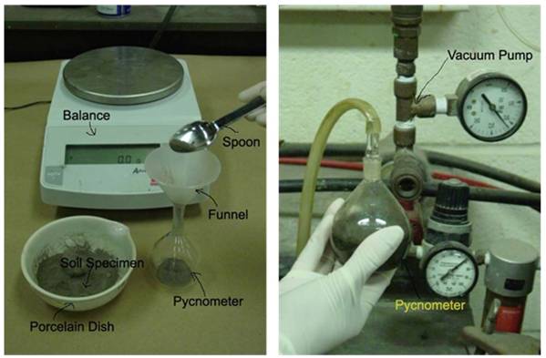
Test Procedure:
(1) Determine and record the weight of the empty clean and dry pycnometer, WP.
(2) Place 10g of a dry soil sample (passed through the sieve No.10) in the pycnometer. Determine and record the weight of the pycnometer containing the dry soil, WPS.
(3) Add distilled water to fill about half to three-fourth of the pycnometer. Soak the sample for 10 minutes.
(4) Apply a partial vacuum to the contents for 10 minutes, to remove the entrapped air.
(5) Stop the vacuum and carefully remove the vacuum line from pycnometer.
(6) Fill the pycnometer with distilled (water to the mark), clean the exterior surface of the pycnometer with a clean, dry cloth. Determine the weight of the pycnometer and contents, WB.
(7) Empty the pycnometer and clean it. Then fill it with distilled water only (to the mark). Clean the exterior surface of the pycnometer with a clean, dry cloth. Determine the weight of the pycnometer and distilled water, WA.
(8) Empty the pycnometer and clean it.
Data Analysis:
Calculate the specific gravity of the soil solids using the following formula:
Specific Gravity,GS = W0/(W0 + (WA − WB ))
Where: W0 = weight of sample of oven-dry soil, g = WPS - WP
WA = weight of pycnometer filled with water
WB = weight of pycnometer filled with water and soil
4. GRAIN SIZE ANALYSIS
Purpose: This test is performed to determine the percentage of different grain sizes contained within a soil. The mechanical or sieve analysis is performed to determine the distribution of the coarser, larger-sized particles, and the hydrometer method is used to determine the distribution of the finer particles.
Standard Reference: ASTM D 422 - Standard Test Method for Particle-Size Analysis of Soils
Significance: The distribution of different grain sizes affects the engineering properties of soil. Grain size analysis provides the grain size distribution, and it is required in classifying the soil.
Equipment: Balance, Set of sieves, Cleaning brush, Sieve shaker, Mixer (blender), 152H Hydrometer, Sedimentation cylinder, Control cylinder, Thermometer, Beaker, Timing device. 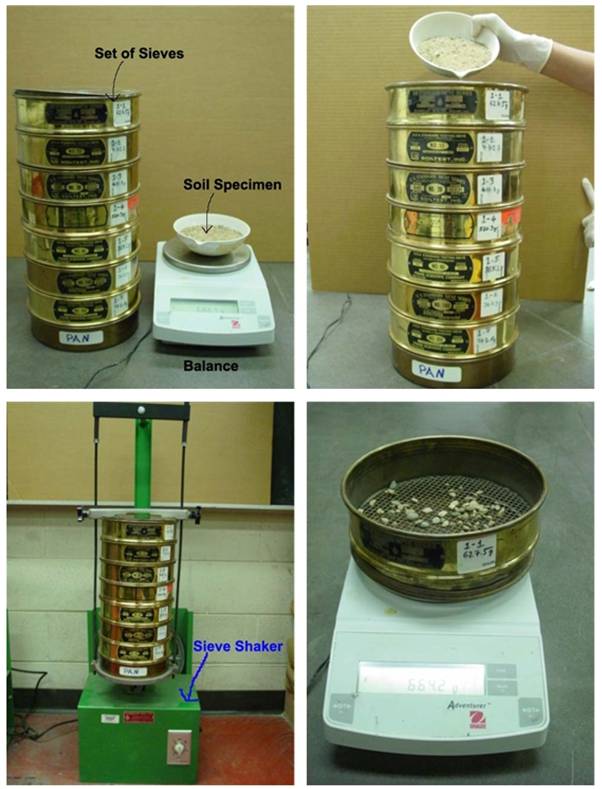
Test Procedure:
Sieve Analysis:
(1) Write down the weight of each sieve as well as the bottom pan to beused in the analysis.
(2) Record the weight of the given dry soil sample.
(3) Make sure that all the sieves are clean, and assemble them in theascending order of sieve numbers (#4 sieve at top and #200 sieve atbottom). Place the pan below #200 sieve. Carefully pour the soilsample into the top sieve and place the cap over it.
(4) Place the sieve stack in the mechanical shaker and shake for 10minutes.
(5) Remove the stack from the shaker and carefully weigh and record the weight of each sieve with its retained soil. In addition, remember to weigh and record the weight of the bottom pan with its retained fine soil.
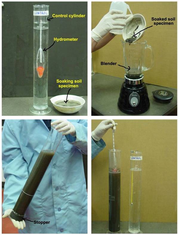
Hydrometer Analysis:
(1) Take the fine soil from the bottom pan of the sieve set, place it into a beaker, and add 125 mL of the dispersing agent (sodium hexametaphosphate (40 g/L)) solution. Stir the mixture until the soil is thoroughly wet. Let the soil soak for at least ten minutes.
(2) While the soil is soaking, add 125mL of dispersing agent into the control cylinder and fill it with distilled water to the mark. Take the reading at the top of the meniscus formed by the hydrometer stem and the control solution. A reading less than zero is recorded as a negative (-) correction and a reading between zero and sixty is recorded as a positive (+) correction. This reading is called the zero correction. The meniscus correction is the difference between the top of the meniscus and the level of the solution in the control jar (Usually about +1). Shake the control cylinder in such a way that the contents are mixed thoroughly. Insert the hydrometer and thermometer into the control cylinder and note the zero correction and temperature respectively.
(3) Transfer the soil slurry into a mixer by adding more distilled water, if necessary, until mixing cup is at least half full. Then mix the solution for a period of two minutes.
(4) Immediately transfer the soil slurry into the empty sedimentation cylinder. Add distilled water up to the mark.
(5) Cover the open end of the cylinder with a stopper and secure it with the palm of your hand. Then turn the cylinder upside down and back upright for a period of one minute. (The cylinder should be inverted approximately 30 times during the minute.)
(6) Set the cylinder down and record the time. Remove the stopper from the cylinder. After an elapsed time of one minute and forty seconds, very slowly and carefully insert the hydrometer for the first reading. (Note: It should take about ten seconds to insert or remove the hydrometer to minimize any disturbance, and the release of the hydrometer should be made as close to the reading depth as possible to avoid excessive bobbing).
(7) The reading is taken by observing the top of the meniscus formed by the suspension and the hydrometer stem. The hydrometer is removed slowly and placed back into the control cylinder. Very gently spin it in control cylinder to remove any particles that may have adhered.
(8) Take hydrometer readings after elapsed time of 2 and 5, 8, 15, 30, 60minutes and 24 hours.
Data Analysis:
Sieve Analysis:
(1) Obtain the mass of soil retained on each sieve by subtracting the weight of the empty sieve from the mass of the sieve + retained soil, and record this mass as the weight retained on the data sheet. The sum of these retained masses should be approximately equals the initial mass of the soil sample. A loss of more than two percent is unsatisfactory.
(2) Calculate the percent retained on each sieve by dividing the weight retained on each sieve by the original sample mass.
(3) Calculate the percent passing (or percent finer) by starting with 100 percent and subtracting the percent retained on each sieve as a cumulative procedure.
(4) Make a semilogarithmic plot of grain size vs. percent finer.
(5) Compute Cc and Cu for the soil.
Hydrometer Analysis:
(1) Apply meniscus correction to the actual hydrometer reading.
(2) From obtain the effective hydrometer depth L in cm (formeniscus corrected reading).
(3) For known GS of the soil (if not known, assume 2.65 for this lab purpose), obtain the value of K
(4) Calculate the equivalent particle diameter by using the following formula:
D = K√L/ t Where t is in minutes, and D is given in mm.
(5) Determine the temperature correction CT.
(6) Determine correction factor “a” using GS.
(7) Calculate corrected hydrometer reading as follows:
RC = RACTUAL - zero correction + CT
(8) Calculate percent finer as follows:
P = ((Rc × a)/WS) × 100
Where WS is the weight of the soil sample in grams.
(9) Adjusted percent fines as follows:
PA = (P x F200 )/100
F200 = % finer of #200 sieve as a percent
(10) Plot the grain size curve D versus the adjusted percent finer on the semilogarithmic sheet.
5. ATTERBERG LIMITS
Purpose: This lab is performed to determine the plastic and liquid limits of a fine-grained soil. The liquid limit (LL) is arbitrarily defined as the water content, in percent, at which a pat of soil in a standard cup and cut by a groove of standard dimensions will flow together at the base of the groove for a distance of 13 mm (1/2 in.) when subjected to 25 shocks from the cup being dropped 10 mm in a standard liquid limit apparatus operated at a rate of two shocks per second. The plastic limit (PL) is the water content, in percent, at which a soil can no longer be deformed by rolling into 3.2 mm (1/8 in.) diameter threads without crumbling.
Standard Reference: ASTM D 4318 - Standard Test Method for Liquid Limit, Plastic Limit, and Plasticity Index of Soils
Significance: The Swedish soil scientist Albert Atterberg originally defined seven “limits of consistency” to classify fine-grained soils, but in current engineering practice only two of the limits, the liquid and plastic limits, are commonly used. (A third limit, called the shrinkage limit, is used occasionally.) The Atterberg limits are based on the moisture content of the soil. The plastic limit is the moisture content that defines where the soil changes from a semi-solid to a plastic (flexible) state. The liquid limit is the moisture content that defines where the soil changes from a plastic to a viscous fluid state. The shrinkage limit is the moisture content that defines where the soil volume will not reduce further if the moisture content is reduced. A wide variety of soil engineering properties have been correlated to the liquid and plastic limits, and these Atterberg limits are also used to classify a fine-grained soil according to the Unified Soil Classification system or AASHTO system.
Equipment: Liquid limit device, Porcelain (evaporating) dish, Flat grooving tool with gage, Eight moisture cans, Balance, Glass plate, Spatula, Wash bottle filled with distilled water, Drying oven set at 105°C. 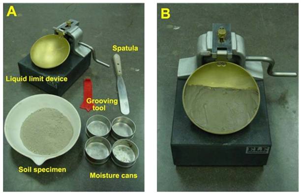
Test Procedure:
Liquid Limit:
(1) Take roughly 3/4 of the soil and place it into the porcelain dish. Assume that the soil was previously passed though a No. 40 sieve, air-dried, and then pulverized. Thoroughly mix the soil with a small amount of distilled water until it appears as a smooth uniform paste. Cover the dish with cellophane to prevent moisture from escaping.
(2) Weigh four of the empty moisture cans with their lids, and record the respective weights and can numbers on the data sheet.
(3) Adjust the liquid limit apparatus by checking the height of drop of the cup. The point on the cup that comes in contact with the base should rise to a height of 10 mm. The block on the end of the grooving tool is 10 mm high and should be used as a gage. Practice using the cup and determine the correct rate to rotate the crank so that the cup drops approximately two times per second.
(4) Place a portion of the previously mixed soil into the cup of the liquid limit apparatus at the point where the cup rests on the base. Squeeze the soil down to eliminate air pockets and spread it into the cup to a depth of about 10 mm at its deepest point. The soil pat should form an approximately horizontal surface (See Photo B).
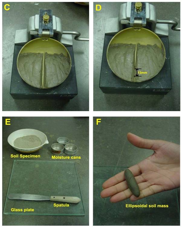
(5) Use the grooving tool carefully cut a clean straight groove down the center of the cup. The tool should remain perpendicular to the surface of the cup as groove is being made. Use extreme care to prevent sliding the soil relative to the surface of the cup (See Photo C).
(6) Make sure that the base of the apparatus below the cup and the underside of the cup is clean of soil. Turn the crank of the apparatus at a rate of approximately two drops per second and count the number of drops, N, it takes to make the two halves of the soil pat come into contact at the bottom of the groove along a distance of 13 mm (1/2 in.) (See Photo D). If the number of drops exceeds 50, then go directly to step eight and do not record the number of drops, otherwise, record the number of drops on the data sheet.
(7) Take a sample, using the spatula, from edge to edge of the soil pat. The sample should include the soil on both sides of where the groove came into contact. Place the soil into a moisture can cover it. Immediately weigh the moisture can containing the soil, record its mass, remove the lid, and place the can into the oven. Leave the moisture can in the oven for at least 16 hours. Place the soil remaining in the cup into the porcelain dish. Clean and dry the cup on the apparatus and the grooving tool.
(8) Remix the entire soil specimen in the porcelain dish. Add a small amount of distilled water to increase the water content so that the number of drops required to close the groove decrease.
(9) Repeat steps six, seven, and eight for at least two additional trials producing successively lower numbers of drops to close the groove. One of the trials shall be for a closure requiring 25 to 35 drops, one for closure between 20 and 30 drops, and one trial for a closure requiring 15 to 25 drops. Determine the water content from each trial by using the same method used in the first laboratory. Remember to use the same balance for all weighing.
Plastic Limit:
(1) Weigh the remaining empty moisture cans with their lids, and record the respective weights and can numbers on the data sheet.
(2) Take the remaining 1/4 of the original soil sample and add distilled water until the soil is at a consistency where it can be rolled without sticking to the hands.
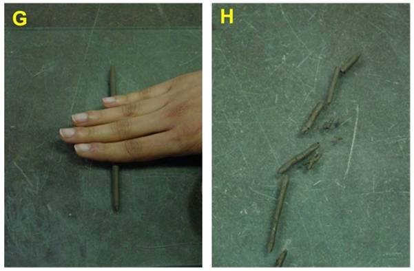
(3) Form the soil into an ellipsoidal mass (See Photo F). Roll the mass between the palm or the fingers and the glass plate (See Photo G). Use sufficient pressure to roll the mass into a thread of uniform diameter by using about 90 strokes per minute. (A stroke is one complete motion of the hand forward and back to the starting position.) The thread shall be deformed so that its diameter reaches 3.2 mm (1/8 in.), taking no more than two minutes.
(4) When the diameter of the thread reaches the correct diameter, break the thread into several pieces. Knead and reform the pieces into ellipsoidal masses and re-roll them. Continue this alternate rolling, gathering together, kneading and re-rolling until the thread crumbles under the pressure required for rolling and can no longer be rolled into a 3.2 mm diameter thread (See Photo H).
(5) Gather the portions of the crumbled thread together and place the soil into a moisture can, then cover it. If the can does not contain at least 6 grams of soil, add soil to the can from the next trial (See Step 6). Immediately weigh the moisture can containing the soil, record its mass, remove the lid, and place the can into the oven. Leave the moisture can in the oven for at least 16 hours.
(6) Repeat steps three, four, and five at least two more times. Determine the water content from each trial by using the same method used in the first laboratory. Remember to use the same balance for all weighing.
Analysis:
Liquid Limit:
(1) Calculate the water content of each of the liquid limit moisture cans after they have been in the oven for at least 16 hours.
(2) Plot the number of drops, N, (on the log scale) versus the water content (w). Draw the best-fit straight line through the plotted points and determine the liquid limit (LL) as the water content at 25 drops.
Plastic Limit:
(1) Calculate the water content of each of the plastic limit moisture cans after they have been in the oven for at least 16 hours.
(2) Compute the average of the water contents to determine the plastic limit, PL. Check to see if the difference between the water contents is greater than the acceptable range of two results (2.6 %).
(3) Calculate the plasticity index, PI=LL-PL. Report the liquid limit, plastic limit, and plasticity index to the nearest whole number, omitting the percent designation.
6. DIRECT SHEAR TEST
Purpose: This test is performed to determine the consolidated-drained shear strength of a sandy to silty soil. The shear strength is one of the most important engineering properties of a soil, because it is required whenever a structure is dependent on the soil’s shearing resistance. The shear strength is needed for engineering situations such as determining the stability of slopes or cuts, finding the bearing capacity for foundations, and calculating the pressure exerted by a soil on a retaining wall.
Standard Reference: ASTM D 3080 - Standard Test Method for Direct Shear Test of Soils Under Consolidated Drained Conditions
Significance: The direct shear test is one of the oldest strength tests for soils. In this laboratory, a direct shear device will be used to determine the shear strength of a cohesionless soil (i.e. angle of internal friction (f)). From the plot of the shear stress versus the horizontal displacement, the maximum shear stress is obtained for a specific vertical confining stress. After the experiment is run several times for various vertical-confining stresses, a plot of the maxi mum shear stresses versus the vertical (normal) confining stresses for each of the tests is produced. From the plot, a straight-line approximation of the Mohr-Coulomb failure envelope curve can be drawn, f may be determined, and, for cohesionless soils (c = 0), the shear strength can be computed from the following equation: s = s tan f
Equipment: Direct shear device, Load and deformation dial gauges, Balance.
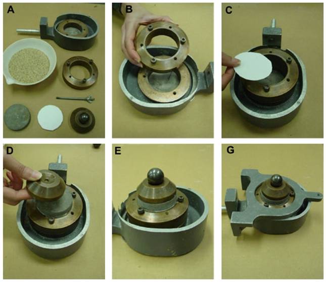
Test Procedure:
(1) Weigh the initial mass of soil in the pan.
(2) Measure the diameter and height of the shear box. Compute 15% of thediameter in millimeters.
(3) Carefully assemble the shear box and place it in the direct shear device. Then place a porous stone and a filter paper in the shear box.
(4) Place the sand into the shear box and level off the top. Place a filter paper, a porous stone, and a top plate (with ball) on top of the sand.
(5) Remove the large alignment screws from the shear box! Open the gap between the shear box halves to approximately 0.025 in. using the gapscrews, and then back out the gap screws.
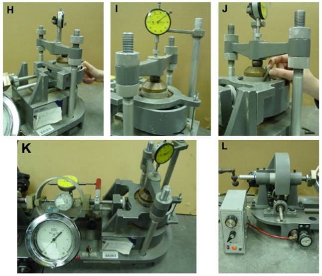
(6) Weigh the pan of soil again and compute the mass of soil used.
(7) Complete the assembly of the direct shear device and initialize the threegauges (Horizontal displacement gage, vertical displacement gage andshear load gage) to zero.
(8) Set the vertical load (or pressure) to a predetermined value, and then closebleeder valve and apply the load to the soil specimen by raising the toggle switch.
(9) Start the motor with selected speed so that the rate of shearing is at a selected constant rate, and take the horizontal displacement gauge, vertical displacement gage and shear load gage readings. Record the readings on the data sheet. (Note: Record the vertical displacement gage readings, if needed).
(10) Continue taking readings until the horizontal shear load peaks and then falls, or the horizontal displacement reaches 15% of the diameter.
Analysis:
(1) Calculate the density of the soil sample from the mass of soil and volume ofthe shear box.
(2) Convert the dial readings to the appropriate length and load units and enter the values on the data sheet in the correct locations. Compute the samplearea A, and the vertical (Normal) stress sv.
sv = NV/A
Where: NV = normal vertical force, and sv = normal vertical stress
(3) Calculate shear stress (![]() ) using t = FH/A
) using t = FH/A
Where FH= shear stress (measured with shear load gage)
(4) Plot the horizontal shear stress (![]() ) versus horizontal (lateral) displacement H.
) versus horizontal (lateral) displacement H.
(5) Calculate the maximum shear stress for each test.
(6) Plot the value of the maximum shear stress versus the corresponding vertical stress for each test, and determine the angle of internal friction (f) from the slope of the approximated Mohr-Coulomb failure envelope.
Categorys
Faacebook
Facebook H.A.I